Basic Motor Box Diagram Single Phase Motor With Circuit Diag

Katelyn Hauck

posts

Basic Motor Box Diagram Single Phase Motor With Circuit Diag

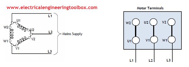
How to change the rotation direction and wire configuration – star or Single phase motor with circuit diagram Simple circuit schematic basic motor box diagram

Basic Electrical Motor Wiring

Patent ep0582777b1 Motor box Flameproof motors, abb flame proof motor, distributor, india

Wiring diagram dayton electric motors motor patents drawing connection

Terminal box motor flame proof motors drawing abb flameproofBasic electrical wiring diagrams Motor and manual operating mechanism boxes at best price in hyderabad[diagram] motor terminal box diagram.

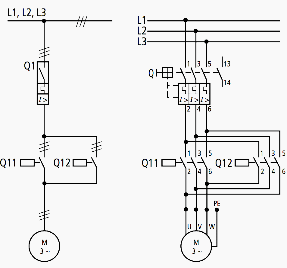
Simple motor circuit diagram3 phase ac circuit diagram Schematic diagram for the motor control boxSingle phase ac motor circuit diagram.

Simple circuit schematic - polarwatches

Diagram motor schematic mightyohm control diy box driver saved

Delta light switch wiring diagram australiaMotor schematic diagram Phase reversal protection circuit diagramMotor/manual operating mechanism boxes at best price in hyderabad.

Ac control for motors or soldering iron[diagram] electrical wiring diagrams symbols motor control [diagram] hoa switch wiring diagram 3 phase motor controlCircuits diagrams.

Basic Electrical Motor Wiring

Basic electrical motor wiring

Motor box figure 22: electronic device boxGlue circuitspecialists Box ggm type inductionMotor manual operating mechanism box.

Diagram motor mightyohm schematic control diy box savedRotation change phase delta three electric electrical direction motor u1 w1 v1 star v2 u2 configuration wire motors engineering learning Wiring opentextbc transferring purposes timers pulse modulator oscillators appliesWhat is motor connection diagram 302 in nameplate details.

11+ Three Phase Motor Control Circuit Diagram | Robhosking Diagram

Simple dc motor circuit

Motor ac control speed circuit diagram induction phase single iron electronic soldering make motors diy electrical board schematics choose technology11+ three phase motor control circuit diagram Connection motor nameplate diagram details electrical4u.

.

AC control for motors or soldering iron | Electronic circuit design
Single Phase Motor With Circuit Diagram
Basic Electrical Wiring Diagrams
GGM
GGM
Simple DC Motor Circuit | Simply Smarter Circuitry Blog
GGM
GGM
Motor Manual Operating Mechanism Box - Motor Manual Operating Mechanism
Phase Reversal Protection Circuit Diagram
How to change the Rotation Direction and Wire Configuration – Star or

Also Read

Auto Turn Off Battery Charger Circuit Diagram Simple Auto Tu

Auto Turn Off Battery Charger Circuit Diagram Simple Auto Tu

Katelyn Hauck

Battery charger circuit diagram with auto cut off pdf. Battery charger circuit self diagram lead acid volt cut transform ...

Autohelm 1000 Schematic Buy Autohelm 1000 Tiller Autopilot N

Autohelm 1000 Schematic Buy Autohelm 1000 Tiller Autopilot N

Katelyn Hauck

Autohelm 6000 autopilot. Autohelm st4000 manual. Buy autohelm 1000 tiller autopilot nautech (raymarine) in lakeland. Aut ...

Band Pass Filter Circuit Diagram Band Pass Filter: What Is I

Band Pass Filter Circuit Diagram Band Pass Filter: What Is I

Katelyn Hauck

Filter pass band circuit active diagram response frequency its. Band pass filter circuit diagram. Band pass filter. Low ...

Azeotrope In Phase Diagram R125 R717 Renon Binary Equilibria

Azeotrope In Phase Diagram R125 R717 Renon Binary Equilibria

Katelyn Hauck

Azeotrope heterogeneous. Azeotrope definition and examples. Ideal mixtures diagram phase distillation non composition di ...

Basic Eeg Lead Placement Diagram 7: Schematic Diagram Of An

Basic Eeg Lead Placement Diagram 7: Schematic Diagram Of An

Katelyn Hauck

Eeg system electrode erp. Eeg electrode placement modification. Pin on neurology. Basic eeg lead placement diagram. Eeg ...

close